13
Oct
How to Estimate the Wear Life of HDPE Slurry Pipes in Mining system
Estimate the remaining wear life of an HDPE slurry pipe by dividing its remaining usable wall thickness by a representative local wear rate. Measure the wall at repeatable inspection points, establish the minimum allowable thickness for the pipe’s operating duty, and update the estimate as new readings become available.
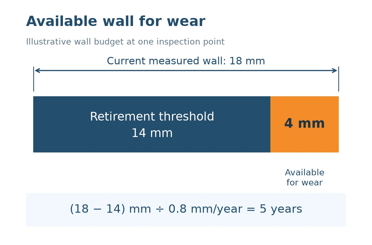
Remaining wear life ≈ (current wall thickness − retirement thickness) ÷ local wear rate.
Use consistent units: a thickness difference in millimetres divided by millimetres per year gives years. Apply the calculation to each critical location; the earliest retirement threshold governs the replacement plan for the assessed section. This predicts time to a wear threshold under the assumed duty, rather than the pipe’s total material service life.
In mining, mineral processing, and tailings transport, pipeline wear affects reliability, shutdown planning, and total cost of ownership. A useful estimate combines slurry properties, operating conditions, pipe design, and measured wall loss. This article explains the main influences, practical estimation methods, and ways to manage wear.
1. Why Wear-Life Estimation Matters So Much
Local wall loss can cause leakage, environmental contamination, and shutdowns. Replacement requires material and labour, while unplanned stoppages can interrupt concentrator or tailings-facility operations.
The practical questions are:
- Under the actual slurry and operating duty, when will a critical section reach its retirement thickness?
- Which locations are losing wall fastest, and how can that loss be detected early?
- How much extra wall can be allocated to wear while maintaining the required pressure-bearing thickness?
For material selection, see our HDPE versus steel comparison for slurry transport. Wear-life assessment then turns that material choice into an inspection and replacement plan.
2. How Wear Occurs in HDPE Slurry Pipes
Slurry wear combines particle impingement and sliding or cutting contact at the pipe wall. The mechanism changes with particle properties and flow conditions, so straight runs, bends, and transitions can develop different wear patterns.
- Circumferential position matters. Settling and moving-bed flow can concentrate wear in the lower portion of a horizontal pipe. Map the circumference rather than measuring only the accessible top surface.
- Changes in flow deserve attention. Bends, reducers, valves, joint misalignment, and internal fusion beads can create turbulence and concentrated particle contact.
- Velocity influences wear and settling. Higher velocity can increase particle impact, while insufficient velocity can allow deposition and moving-bed wear. Establish an operating window for the actual slurry.
- Particle characteristics affect the wear mechanism. Hardness, angularity, size distribution, and density influence cutting and impact at the wall.
Vinidex’s PE slurry guidance describes the effects of particles, velocity, impact angle, and local flow disturbances. These are useful inputs for locating inspection points and interpreting measured wall loss.
3. Key Factors Affecting Wear Life
Slurry characteristics
Record particle hardness and shape, the particle-size distribution, and the proportion of coarse particles. D50 is the median particle size by the stated distribution basis; include that basis and the coarse tail of the distribution in the record.
Also record solids concentration, whether expressed by mass or volume, slurry density, temperature, and the liquid chemistry. Consistent concentration units make reference data and operating records easier to compare.
ASTM G75-24 provides a laboratory procedure for the relative abrasivity of a slurry, expressed as the Miller Number, and the abrasion response of a selected material, expressed as the SAR Number. The distinction matters: a Miller Number ranks a slurry against the standard reference specimen, while a SAR test evaluates the selected material in that slurry. Use these indices to support testing and material comparison; derive pipe wall-loss rates from representative pipe tests or field measurements.
Operating parameters
Record actual velocity, flow stability, starts and stops, pressure transients, and operating hours. Determine the transport velocity from the measured slurry behaviour and the selected bore, with an operating margin that accommodates normal variations in solids and flow.
Use either calendar time or operating hours consistently in the wear-rate calculation. If the slurry duty changes, record when it changed so that wall-loss trends can be separated by duty.
The pipe itself
Record the material designation, actual dimensions, SDR, initial wall map, ovality, and joint details. PE100-RC improves resistance to slow crack growth, as explained by the PE100+ Association. Abrasive wall loss remains a separate property to establish for the slurry duty.
Define the usable wear allowance as the thickness above the approved retirement threshold. That threshold must retain the wall needed for pressure, temperature, surges, and relevant structural loads, with the inspection and replacement margin included.
System layout
Review bend radius, reducers, valves, pump discharge arrangements, elevation changes, and horizontal runs. Assign inspection points to the locations most likely to concentrate particle contact or disturb the flow, rather than relying on a pipeline-wide average.
4. Practical Estimation Methods
Empirical calculations and reference data
Begin with wall-loss rates from comparable operating records or representative testing. Compare particle characteristics, concentration, velocity, pipe material, bore, geometry, temperature, and duty before transferring a rate to a new section.
Some empirical models express wear rate as a power of velocity. Use a fitted exponent only within the slurry, material, geometry, and velocity range represented by the calibration data. Establish separate estimates for normal and more abrasive duty instead of inserting a generic exponent into every project.
Accelerated laboratory testing
Slurry-loop or rotating-pipe tests can compare candidate materials under controlled conditions. Record how the test reproduces the particle contact and flow regime expected in the pipeline. Convert mass or volume loss to a wall-loss estimate using the relevant specimen geometry, then compare that estimate with field observations.
Miller and SAR testing add information about relative abrasivity and material response. A pipe wear-life calculation also needs a representative wall-loss rate and a defined retirement threshold.
Field measurement and back-calculation
Establish repeatable locations around the circumference and along the route. Take a baseline survey before service or at the start of the assessment, then measure the same positions after a known period of operation.
For a monitoring point with thickness readings t₁ and t₂:
Local wear rate r ≈ (t₁ − t₂) ÷ elapsed time.
Then:
Remaining wear life L ≈ (t₂ − t_retire) ÷ r.
Here t_retire is the approved retirement thickness, including the replacement margin. A thickness already at or below that threshold requires action under the operating plan, rather than a positive remaining-life estimate.
Ultrasonic thickness measurement can be used on plastic pipe without accessing the bore. Evident’s plastic-pipe application note explains the need to select suitable equipment, calibrate sound velocity on the material being measured, and use couplant at the probe contact. Validate the setup against a known-thickness PE sample and record measurement uncertainty before interpreting small differences as wear.
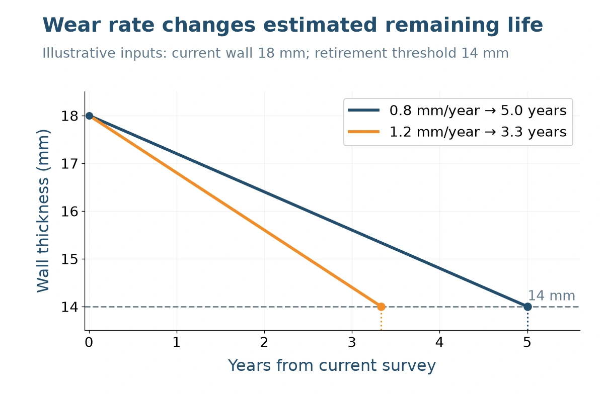
As an illustrative calculation, a monitored point with a current wall thickness of 18 mm, an approved retirement thickness of 14 mm, and a representative local wear rate of 0.8 mm/year has an estimated 5 years to that threshold: (18 − 14) ÷ 0.8 = 5. If a more abrasive duty produces 1.2 mm/year, the same remaining allowance gives about 3.3 years. These are calculation examples, not Puhui product performance figures.
Numerical simulation for complex layouts
CFD coupled with a suitable wear model can help identify likely high-wear zones in complex bends, transitions, or pump-discharge arrangements. Compare predicted patterns with inspection results and calibrate the model before using it to set replacement timing.
Present a base estimate and a conservative scenario using explicit assumptions about local wear rate, duty, and measurement uncertainty. Set the inspection interval early enough to detect changes before the retirement threshold is reached.
5. Actionable Estimation Steps
- Gather baseline data. Collect slurry analysis, concentration, actual velocity, operating hours, pipe dimensions, material, and layout drawings.
- Identify critical locations. Include bends, reducers, disturbed-flow sections, pump discharges, and the lower circumference of horizontal runs where settling is expected.
- Establish a local wear rate. Use representative reference data or repeated measurements at matching locations; keep calendar years and operating hours distinct.
- Approve the retirement thickness. Account for pressure-temperature duty, surges, structural loads, measurement uncertainty, and replacement lead time.
- Calculate time to the threshold. Divide the remaining usable thickness by the local rate, and compare normal and conservative duty scenarios.
- Create an inspection and action plan. Survey more frequently while establishing the initial trend, then revise intervals using the observed rate and remaining margin.
Keep the measurements, operating conditions, assumptions, and calculation revision together so that a change in the estimate can be traced to evidence.
6. How to Meaningfully Extend Actual Service Life
- Control the operating window. Maintain transport while reducing unnecessary particle impact; watch for changes in solids distribution and pump performance.
- Improve the layout. Use suitable bend radii and smooth bore transitions. Consider replaceable wear sections at locations where loss is concentrated.
- Select material and wall together. Establish the pressure-bearing requirement and planned wear allowance before choosing the SDR and minimum wall.
- Manage circumferential wear. Where a flanged-spool layout and the maintenance plan permit pipe rotation, use inspection records to redistribute localized bottom wear. Shut down, isolate, and support the section according to the site’s procedure before repositioning it.
- Maintain installation quality. Alignment, support, and controlled joint geometry help avoid local loads and flow disturbances.
Evaluate each measure by its effect on the critical location and the maintenance plan, rather than by added wall thickness alone.
7. Typical Observations and Lessons
A section average can conceal a thin local area. A satisfactory straight-run reading can coexist with faster loss at a bend or transition. Plot readings by position, date, and duty so that the controlling location remains visible.
If particle size, concentration, or operating hours change, review the wear trend and inspection schedule. If successive readings show little change relative to measurement uncertainty, extend the observation period or improve measurement repeatability before fitting a rate.
Once sufficient data exist, compare earlier predictions with the measured wall map. Use that comparison to improve the next estimate and the replacement plan.
8. Summary and Recommended Next Steps
An actionable wear-life estimate needs three quantities: the current local wall thickness, an approved retirement thickness, and a representative local wear rate. Slurry properties and operating records explain the rate; repeated measurements keep the estimate current.
For an existing line, compile the pipe and slurry information, survey the critical locations, and calculate time to the approved threshold. For a new line, establish a provisional wear rate from representative evidence and plan the first field surveys to check it.
Use the estimate to schedule inspection, optimize operation, and prepare replacement before the controlling section reaches its retirement threshold.