
14
Oct
How to Determine the Diameter and Conveying Velocity of HDPE Mining Slurry Pipes
Determine pipe diameter and conveying velocity together: establish the slurry flow range, identify the minimum transport velocity for the slurry, and select an HDPE pipe bore that meets that velocity at the lowest continuous flow. Then check pressure loss, wear and pump duty across the full operating range. A diameter that works at peak throughput can still allow deposition when production slows.
Key Factors That Control Diameter and Velocity
Start with accurate data on the slurry and the route:
- Design flow rate at normal, minimum and maximum operation.
- Solids concentration, clearly identified as mass or volume concentration.
- Particle density, size distribution, D50, maximum particle size and shape.
- Slurry density and rheology at operating temperature and concentration.
- Pipeline length, elevation change, slopes, bends, valves and discharge conditions.
Use the pipe’s actual internal diameter in hydraulic calculations. HDPE pipes with the same outside diameter can have different wall thicknesses and bores. A thicker wall reduces the internal diameter and increases velocity at the same flow rate. The HDPE pipe specification and size table is a useful starting point for matching outside diameter and wall thickness.
How to Set the Correct Conveying Velocity
For a settling slurry, insufficient velocity allows particles to accumulate along the bottom of the pipe. The developing bed reduces the available flow area and can increase local wear and pressure loss. Excessive velocity can raise abrasive wear and pumping demand.
Set the operating range in three steps:
- Determine the critical deposition or minimum transport velocity for the specific slurry and candidate pipe bore, using a suitable correlation and representative slurry testing.
- Set an operating margin that covers variation in flow, particle size and concentration, together with control and measurement uncertainty.
- Confirm that velocity stays above the resulting minimum throughout continuous operation, including the lowest expected flow rate.
The deposition threshold marks the onset of solids accumulating at the pipe bottom; it does not mean every particle is uniformly suspended. Vinidex’s PE slurry-flow guidance describes this minimum and recommends iterative sizing supported by flow testing.
There is no single best velocity or fixed margin for every mining slurry. Select the calculation method to suit the particle distribution, concentration and flow behaviour. Durand-type methods can support assessment of settling slurries; thickened, non-Newtonian slurry also requires rheological data for its operating conditions. KSB’s solids-transport guidance explains how velocity, particle size and concentration affect transport and clogging risk.
How to Select the Pipe Diameter
For a full circular pipe, average velocity follows the continuity relationship:
v = 4Q / (π × Dᵢ²)
Rearrange it to calculate the required internal diameter at a selected velocity:
Dᵢ = √[4Q / (π × v)]
Here, v is average velocity in m/s, Q is the total slurry volumetric flow rate in m³/s, and Dᵢ is internal diameter in metres. Convert flow in m³/h to m³/s by dividing by 3,600, and convert diameter in millimetres to metres by dividing by 1,000.
As an illustrative calculation, Q = 180 m³/h = 0.050 m³/s and v = 2.0 m/s give Dᵢ ≈ 0.178 m, or 178 mm. This calculation finds the bore corresponding to the chosen inputs. The velocity target is established separately from slurry transport requirements.
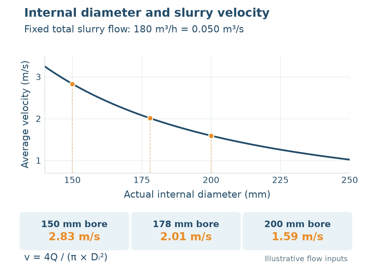
Choose candidate standard outside diameters and SDRs, then calculate velocity using each candidate’s actual bore. SDR is the nominal outside diameter divided by nominal wall thickness. For an initial geometric estimate, internal diameter is outside diameter minus twice the wall thickness; use the supplier’s dimension table and tolerances for the final hydraulic model. Vinidex’s pipe-and-fittings catalogue illustrates how the bore changes between SDR classes.
At a fixed flow rate, a smaller bore raises velocity and usually increases friction loss. A larger bore reduces velocity and may lower pumping demand, but can increase deposition risk at low flow. Compare each candidate’s minimum-flow velocity with its own deposition threshold, because pipe diameter also affects that threshold.
Select wall thickness for operating pressure, temperature, surge, installation loads and the required wear allowance. Recalculate the bore after selecting the SDR. Assess expected abrasion alongside hydraulic performance using the methods described in estimating the wear life of HDPE slurry pipes.
Practical Design Sequence
- Characterise the slurry: concentration, particle size, density and rheology.
- Define the normal, minimum and maximum total slurry flow rates.
- Estimate the deposition threshold for candidate bores and set the minimum operating velocity.
- Select candidate outside diameters and SDRs that meet pressure and structural requirements.
- Calculate velocity and slurry pressure loss for each candidate, including fittings and elevation change.
- Check pump duty, power, abrasion and overall system cost.
- Verify the lowest continuous flow, together with startup, shutdown and flushing arrangements; revise the sizing or operating strategy where required.
For heterogeneous or non-Newtonian slurry, use a hydraulic model that represents the actual mixture. The continuity formula remains applicable, but clean-water flow charts alone do not determine slurry pressure loss or a suitable transport velocity.
Common Mistakes to Avoid
- Applying one fixed velocity to every slurry or using clean-water charts as a complete slurry design method.
- Calculating velocity from outside diameter instead of the actual internal diameter after SDR selection.
- Designing only for maximum throughput and overlooking minimum continuous flow.
- Mixing mass and volume concentration, or using solids throughput as total slurry volumetric flow.
- Ignoring local restrictions, bends, reducers and pump-discharge conditions when checking loss and wear.
- Omitting representative slurry testing where uncertainty in transport behaviour determines the sizing decision.
Conclusion
Diameter and conveying velocity must be selected together from slurry properties and the full operating flow range. Establish the transport threshold, calculate candidate bores, and verify minimum-flow velocity, pressure loss, wear and pump duty. Confirm the actual bore of the selected HDPE pipe before finalising the design.
Visit our hdpe pipe and fittings or speak with our engineering team for technical support and project references.